Views: 0 Author: Site Editor Publish Time: 2026-08-04 Origin: Site

The operational lifespan and safety of a steam shower rely heavily on the precision of its plumbing connections, not just the electrical setup. When contractors treat a steam bath generator like a standard residential water heater, the system is practically guaranteed to fail. Improper water feeds or inadequate drainage lead directly to premature element failure, severe scale accumulation, voided warranties, and catastrophic water damage behind finished walls.
We see these failures constantly in the field. A burned-out inlet solenoid or a melted PVC drain pipe usually stems from a fundamental misunderstanding of high-temperature plumbing requirements. This guide serves as a technical blueprint for evaluating and executing the water supply and drain line connections for a steam unit. We will focus strictly on code compliance, material selection, and mechanical risk mitigation to ensure the rough-in phase sets the foundation for a reliable, long-lasting installation.
Material Constraints: Copper or cross-linked polyethylene (PEX) are standard for supply lines, but drain lines often require heat-resistant materials (like copper or cast iron) due to high-temperature discharge.
Valve Placement: A dedicated, easily accessible shut-off valve must be installed on the water supply line upstream of the generator to allow for maintenance without disrupting the entire property's water supply.
Drainage Protocol: Generators require a dedicated gravity-fed drain line, often necessitating an indirect waste connection or air gap to comply with local plumbing codes and prevent backflow.
Pre-Connection Flushing: Failing to completely flush the water supply line before final connection is a primary cause of inlet solenoid valve failure due to construction debris.
Before you cut a single pipe or sweat a fitting, you have to establish the physical and mechanical parameters of the installation space. The location of the unit dictates the complexity of your plumbing routes. You will typically install these units in nearby closets, heated attics, vanities, or dedicated mechanical rooms. The absolute non-negotiable requirement is that the unit remains fully accessible. You will need to perform plumbing maintenance, clean inline filters, and service the auto-flush mechanisms. Sealing the unit behind drywall without a generously sized access panel is a massive mistake that will require destructive demolition later.
You must evaluate the specific manufacturer specifications found in the rough-in guides. Do not assume universal sizing. Thread sizes, required water pressure (which typically ranges from 15 to 70 PSI), and flow rates vary significantly depending on the unit's size and the brand you are installing. A compact residential unit has vastly different mechanical requirements than a high-capacity commercial system.
Plumbing requirements and rough-ins scale directly based on the kilowatt rating of the Professional Steam Bath Machine. These units can range from compact 4.5kW models up to heavy-duty 15kW+ systems. As the kW rating increases, so does the volume of water it processes and the amount of steam it outputs, which changes your pipe sizing requirements.
Local municipal plumbing codes regarding backflow prevention, indirect waste requirements, and maximum discharge temperatures must be verified before starting the job. Code compliance ensures safety and prevents inspectors from forcing costly tear-outs. Furthermore, when integrating the generator alongside high-end multi-fixture setups like dual showerheads or massive rain panels, you have to carefully plan the layout. You want to avoid pressure drops across the water supply system when multiple fixtures run simultaneously.
| Generator Capacity (kW) | Typical Water Feed Size | Typical Steam Line Size | Recommended Drain Size |
|---|---|---|---|
| 4.5kW - 7.5kW | 3/8 inch | 1/2 inch | 1/2 inch to 3/4 inch |
| 7.5kW - 12kW | 3/8 inch to 1/2 inch | 3/4 inch | 3/4 inch |
| 12kW - 15kW+ | 1/2 inch | 3/4 inch to 1 inch | 3/4 inch to 1 inch |
Copper and PEX are the standard choices for running the water feed. Copper offers exceptional durability and rigidity, making it ideal for exposed runs in mechanical rooms where pipes might get bumped. PEX is highly flexible, much easier to route through existing framing, and generally faster to install on the job site. While PEX is perfectly acceptable for the cold water feed in most jurisdictions, you have to be careful at the connection point. The connections directly at the generator must account for ambient heat radiating from the tank. Always ensure the PEX transitions to a suitable brass or copper fitting a few inches away before attaching to the generator housing.
You must install an inline shut-off valve located upstream of the generator. This allows you to isolate the unit for maintenance, filter changes, or emergency repairs without shutting down the main water supply to the rest of the building. If the municipal water supply exceeds the manufacturer's maximum PSI threshold, installing a water pressure regulator is mandatory. High pressure will rupture internal diaphragms and cause the unit to leak continuously.
There is a major implementation risk here regarding inlet solenoid protection. Never solder fittings while they are directly attached to the generator. The heat transfer travels straight down the copper and will permanently destroy the internal inlet solenoid valve. The safety protocol is simple: solder all your copper adapters on a workbench, let them cool completely, and only then thread them into the solenoid valve using Teflon tape or pipe dope.
Manufacturer guidelines usually specify connecting the unit to a cold water feed. Cold water is standard because it minimizes the risk of premature component degradation. If you decide to use a hot water feed, it must strictly not exceed 160°F. Anything hotter will damage the internal diaphragms and rubber gaskets inside the solenoid.
Flushing the water supply line completely into a bucket is a critical step that many installers skip. You must clear all copper shavings, excess flux, and sediment from the line before threading it to the generator. If construction debris enters the solenoid valve, it will cause the valve to stick open. This leads to continuous filling, water running out of the steam head, and potential flooding.
Hard water severely impacts the performance and lifespan of the equipment. Calcium and magnesium rapidly form scale on the heating elements. This scale acts as an insulator, reducing heating efficiency, and eventually causes the elements to overheat and fail. Integrating inline water softeners or scale-inhibitor filters on the supply line protects the heating elements and drastically reduces maintenance frequency.
| Water Hardness Level | Impact on Generator | Recommended Filtration Strategy |
|---|---|---|
| 0 - 3 GPG (Soft) | Minimal scale buildup. | Standard inline sediment filter. |
| 3 - 7 GPG (Moderate) | Gradual scale accumulation on elements. | Scale-inhibitor cartridge. |
| 7+ GPG (Hard) | Rapid element failure, frequent blockages. | Dedicated water softening system. |
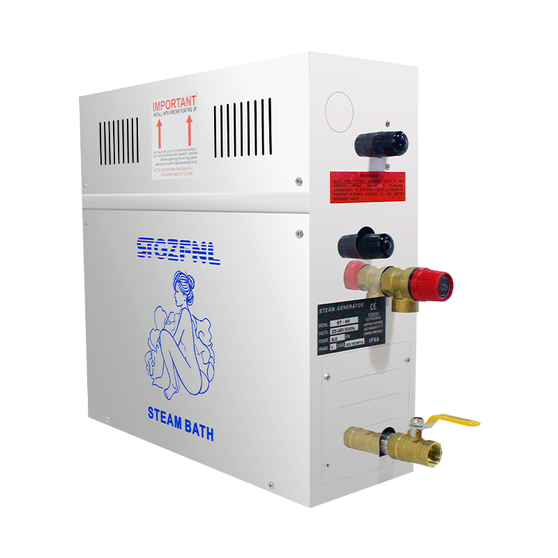
A steam unit requires a dedicated drain line. You cannot simply tap directly into the shower's primary P-trap. The discharge volume and the extreme temperature of the purged water can easily overwhelm standard shower drains. Gravity drainage is the only acceptable method here. The drain line requires a consistent pitch, typically 1/4 inch per foot, to ensure complete evacuation of the tank. If the pipe is flat or pitched backward, stagnant water will sit in the tank and lines, leading to bacterial growth and accelerated scale formation.
Using standard PVC for the drain line poses significant risks and is a common code violation. The purged water from the tank can easily exceed PVC's maximum temperature rating, often reaching near-boiling temperatures during an auto-flush cycle. This thermal shock leads to warping, joint failure, leaks, or toxic off-gassing. You must use high-temperature rated materials such as copper, CPVC, or cast iron for the immediate discharge route.
The auto-flush valve is a motorized mechanism that automatically purges stagnant water and loose scale from the tank after each use. This component significantly extends the generator's lifespan. During initial commissioning or when performing manual maintenance runs, you need to follow a specific mechanical sequencing to clear the line effectively:
Open the water inlet cock to allow full flow into the tank.
Shut the steam outlet cock to build slight internal pressure.
Execute the surging protocol on the drain cock to break up settled sediment at the bottom of the tank.
Keep the drain cock fully open to verify clear, uninhibited water passage into the waste line.
Re-open the steam cock and close the manual drain bypass to restore normal operation.
Plumbing codes generally require routing the generator drain to an indirect waste receptor. This usually means discharging the pipe over a floor drain, a mop sink, or a specialized hub drain with an appropriate air gap. This setup is a critical risk mitigation strategy. It prevents hazardous sewer gases or contaminated wastewater from backing up into the clean steam generator tank if the main sewer line clogs. The air gap provides a physical, visible break between the discharge pipe and the building's drainage system.
The steam line carrying the vapor from the generator to the shower enclosure must be constructed of rigid copper or brass. Never use PEX or PVC for the steam line. Plastic pipes will melt, deform, or degrade rapidly under continuous 212°F+ steam exposure. Standard sizing for the steam line is usually 1/2-inch to 3/4-inch, depending entirely on the generator's kW rating and the manufacturer's output fitting. Ensure all copper joints are properly cleaned, fluxed, and soldered to prevent steam leaks inside the wall cavity.
You must pitch the steam line either back toward the generator or forward toward the steam head. The pipe cannot have any dips or sags. Proper pitch prevents condensation from pooling inside the pipe. Pooled water creates water traps, which block the flow of steam and cause violent sputtering or "water spitting" at the steam head, which can burn the user. Furthermore, insulating the steam line with high-temperature fiberglass or closed-cell foam is absolutely necessary. Insulation prevents heat loss as the steam travels through cold wall cavities, minimizes condensation inside the pipe, and protects surrounding wood framing and drywall from heat damage.
The reliability of a steam shower is directly proportional to strict adherence to plumbing fundamentals. Proper pressure regulation, temperature-appropriate materials, and gravity drainage dictate the system's longevity. A professional installation mitigates the risks of component failure and water damage.
Finalize your unit sizing based on the exact cubic footage and material finish of your shower enclosure.
Test your home's static water pressure and water hardness to determine if you need a pressure reducing valve or an inline scale filter.
Consult with a licensed plumber to map out the rough-in routing for the indirect waste line before purchasing materials.
Install a dedicated, accessible shut-off valve on the cold water feed immediately outside the generator housing.
A: Most manufacturers require connecting to a cold water supply. If hot water is used, it must strictly not exceed 160°F to prevent permanent damage to internal diaphragms, gaskets, and the solenoid valve.
A: No. The purged water from the tank is often near boiling and exceeds the temperature rating of standard PVC. This causes warping, joint failure, and leaks. You must use copper, CPVC, or cast iron.
A: The water supply line is typically 3/8-inch or 1/2-inch. The exact size depends on the manufacturer's specifications, the flow rate requirements, and the generator's specific kilowatt rating.
A: Yes. It requires a dedicated gravity-fed drain line routed to an indirect waste receptor with an air gap. This complies with plumbing codes and prevents contaminated water from backing up into the unit.
A: An inline shut-off valve must be installed on the water supply line upstream of the generator. It should be placed in an easily accessible location to allow for routine maintenance and emergency shut-offs.
A: Flushing removes copper shavings, flux, and sediment from the pipes. If this debris enters the inlet solenoid valve, it will cause the valve to stick open, leading to continuous filling and flooding.
A: Solder all copper adapters on a workbench and allow them to cool completely. Once cool, thread them into the solenoid valve using Teflon tape. Direct heat transfer from a torch will destroy the internal components.


